
TL494CDR
The TL494 is a fixed-frequency PWM controller for switch-mode power supplies supporting boost, buck, flyback, push-pull, and SEPIC topologies. It integrates two error amplifiers, a dead-time control comparator with up to 45% duty cycle, and an adjustable oscillator up to 300kHz. It is widely used in off-line and DC/DC power converters.
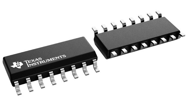
- Package
- SOIC-16 (D)
Product overview
The TL494 is a fixed-frequency PWM controller for switch-mode power supplies supporting boost, buck, flyback, push-pull, and SEPIC topologies. It integrates two error amplifiers, a dead-time control comparator with up to 45% duty cycle, and an adjustable oscillator up to 300kHz. It is widely used in off-line and DC/DC power converters.
- Manufacturer
- TI
- Part number
- TL494CDR
- Category
- Power Management
- Package
- SOIC-16 (D)
- Packaging
- Tape & Reel
- Condition
- New & Original
- Compliance
- RoHS Compliant
- Lifecycle
- Confirm with manufacturer
- Lead time / MOQ
- Confirm with quotation
Technical parameters
27 parametersConstruction
- Human body model (HBM), per ANSI/ESDA/JEDEC JS-001, all pins
- 500
- fOSC Oscillator frequency
- 300 kHz
- CT Timing capacitor
- 0 nF
- RT Timing resistor
- 500 kΩ
- Common source VE = 0, IC = 200mA
- 1.3
- Source follower VO(C1 or C2) = 15V, IE = –200mA
- 2.5
- Maximum duty cycle, each output
- 45%
- Zero duty cycle
- 3.3
- Maximum duty cycle
- 0
- RT = Vref, VCC = 15V
- 10
- All other inputs and outputs open VCC = 40V
- 15
- Rise time
- 200 ns
- Fall time
- 100 ns
Performance
- VCC Supply voltage
- 41 V
- VO Collector output voltage
- 41 V
- IO Collector output current
- 250 mA
- Lead temperature 1,6mm (1/16 inch) from case for 10 seconds
- 260 °C
- Tstg Storage temperature range
- 150 °C
- VI Amplifier input voltage
- 2 V
- Collector output current (each transistor)
- 200 mA
- Current into feedback terminal
- 0.3 mA
- C1, C2 off-state current VCE = 40V, VCC = 40V
- 100 μA
- E1,E2 off-state current VCC = VC = 40V, VE = 0
- 100 μA
- Output control input current VI = Vref
- 3.5 mA
- Input bias current (DEAD-TIME CTRL) VI = 0 to 5.25V
- 10 μA
- Input threshold voltage (FEEDBACK) Zero duty cyle
- 4.5 V
- Input sink current (FEEDBACK) V (FEEDBACK) = 0.7V
- 0.3 mA
Specifications & documentation
Use the official manufacturer documentation to verify electrical characteristics, package dimensions and operating limits before design approval.
Request confirmation of current stock, date code, packaging, price and delivery terms. Product information does not constitute a binding offer; final specifications are confirmed with your quotation.